How to Choose a Vertical Boring Machine?
Choosing a Vertical Boring Machine starts with the part, not the catalogue. A heavy casting on a shop floor looks simple until its diameter, height, mass, and machining allowance meet the machine’s limits. Gardner Intelligence’s 2024 World Machine Tool Survey provides market-level production and consumption data. UNIDO’s International Yearbook of Industrial Statistics 2024 offers broader manufacturing indicators. Neither report chooses a machine for you. They do help frame the investment: demand can shift, while a machine’s capabilities stay fixed for years.
Measure the largest and heaviest workpieces you expect to machine, then allow for future jobs. Compare table diameter, maximum swing, workpiece height, load capacity, spindle torque, ram travel, and required accuracy. Check which operations the machine supports; “vertical boring” and “vertical turning” can describe overlapping equipment, but labels alone do not confirm capability. Details matter. Ask for documented accuracy tests and representative cutting trials, not just headline specifications. ISO 230-1 provides a recognized framework for checking machine-tool geometric accuracy, though acceptance conditions should match your application.
Also inspect the practical details: foundation requirements, chip and coolant handling, tool capacity, control familiarity, service response, and parts availability. Ask the supplier how performance changes under a realistic production cycle. A large table can be reassuring, but it does not guarantee the torque or stiffness a difficult cut needs. Not always. Compare total installation and operating costs, and verify claims in writing. The right choice balances present work, credible future demand, and support your team can actually access. Some uncertainty remains; make it visible before purchase.
Measure Workpiece Diameter, Height, and Mass Against Machine Capacity
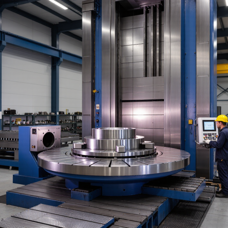
Measure the workpiece before comparing machines. Record its largest diameter, total height, and mass, including any fixture that will rotate with it. A part that measures 1,200 millimeters across may need more than 1,200 millimeters of turning capacity. Allow room for tool movement and safe loading. Check the machine’s maximum turning diameter, table diameter, and available ram travel. These figures describe different limits. Do not treat them as interchangeable.
Mass matters just as much. Compare the combined workpiece-and-fixture weight with the table’s rated load, then check any stated limits for load position or rotational speed. An off-center casting can place uneven force on the table. That detail is easy to miss. Also consider height: a tall part may clear the table but interfere with the cross rail, ram, or overhead equipment. I would verify the setup envelope with a drawing, not rely on a rough estimate. Leave practical clearance for clamping and measurement. If the published capacity is unclear, ask a qualified machine supplier or engineer to confirm the proposed setup; a rating alone may not describe every operating condition.
Match Maximum Turning Diameter and Table Size to the Workpiece (mm)
Choose a vertical boring machine by measuring the workpiece’s full swept envelope, not just its nominal diameter. Include projecting lugs, clamps, and any eccentric features. For a 1,200 mm casting, a 1,400 mm maximum turning diameter may provide useful clearance, but verify the actual setup before selecting capacity. The table must also support the workpiece’s weight and footprint. A large diameter rating does not guarantee enough table area or load capacity.
Gardner Intelligence’s 2023 World Machine Tool Survey estimated global machine-tool consumption at about US$99.5 billion in 2022. That figure reflects broad investment demand, not a sizing rule; confirm machine dimensions against your own parts and fixtures. Check the manufacturer’s stated maximum turning diameter, table diameter, and permissible table load separately. Leave room for safe clamping and tool access. Small details matter.
Tips: Sketch the part and fixture together, then measure the widest rotating point. Compare that measurement with the machine’s rated turning diameter. Check table-load limits with the combined workpiece and fixture weight. If your largest part barely fits, pause and review clearance; I have seen nominal dimensions hide awkward clamp interference. Keep units consistent in mm.
Compare Spindle Power (kW), Torque (N·m), and Speed (r/min)
How to Choose a Vertical Boring Machine?
Compare Spindle Power (kW), Torque (N·m), and Speed (r/min)
When comparing vertical boring machines, don’t judge spindle power alone. A 30 kW spindle may cut steadily at low speed, but its torque depends on the speed at which that power is available. Machinery’s Handbook, 31st edition, gives the standard relationship:
At 120 r/min, 30 kW corresponds to about 2,388 N·m; at 600 r/min, it is about 478 N·m. Same power. Very different cutting feel.
Match the torque curve to the work. Large castings, heavy roughing, and interrupted cuts usually demand strong low-speed torque. Finishing smaller diameters may need higher spindle speed and stable power across the upper range. Ask for continuous-duty power and torque curves, not only maximum ratings. A machine’s peak figure may be available briefly, not throughout a long cut. Check the spindle’s usable speed range against the workpiece diameter and cutting data for its material.
A practical check: compare the curve at your planned cutting speed, then confirm the duty cycle and gearbox limits with the supplier. ISO 14955-1:2017 provides a framework for assessing machine-tool energy use, reminding buyers to consider operating conditions, not just headline ratings. One limitation: published curves may not reflect worn tooling or actual setup stiffness. Request a test cut on a representative workpiece. Numbers help, but the chip tells you more.
Check Table Load (t), T-Slots, and Workholding Requirements
How to Choose a Vertical Boring Machine?
Check Table Load (t), T-Slots, and Workholding Requirements
Start with the table’s rated load, not just the workpiece weight. Include fixtures, clamps, and any support blocks. A 2-ton casting can become a much heavier setup once its fixture is added. Check how the load is distributed, too. A large, uneven casting may stress the table differently from a compact part of equal weight. Confirm the machine’s load rating and setup limits in its technical documentation.
Tips: Measure the T-slot width, spacing, and depth before choosing clamps or fixture plates. Check that your workholding can secure the part without blocking tool travel. Leave room for chip clearance. Small details matter.
Think through how the part will sit and rotate on the table. Will the clamps remain accessible at every machining position? Can the fixture resist cutting forces without shifting? A setup that looks stable while stationary may still vibrate during a heavy cut. It is easy to focus on maximum capacity and overlook access. That happens. Sketching the part, fixture, and clamp positions can reveal problems before installation. If the load is close to the rated limit, ask the machine supplier or a qualified applications engineer to verify the setup.
| Workpiece + Fixture Mass | Suggested Minimum Table Load Rating | Indicative T-Slot Size | Typical Workholding Approach | What to Verify Before Selection |
|---|---|---|---|---|
| Up to 1.5 t | At least 2 t | 14–18 mm slot; commonly paired with M12–M16 fasteners | T-slot clamps, step blocks, or a small dedicated fixture | Table diameter, slot spacing, clamp reach, and clearance for the boring head |
| Over 1.5 t to 3.75 t | At least 5 t | 18–22 mm slot; commonly paired with M16–M20 fasteners | Multiple clamps with step blocks, or a bolted fixture plate | Load distribution across the table and whether the workpiece can be securely located and restrained |
| Over 3.75 t to 7.5 t | At least 10 t | 22–28 mm slot; commonly paired with M20–M24 fasteners | Heavy-duty clamping, a substantial fixture plate, or engineered workholding | Permitted load at the actual workpiece position, table speed limits, and lifting and loading method |
| Over 7.5 t to 15 t | At least 20 t | 28–36 mm slot; commonly paired with M24–M30 fasteners | Engineered fixture or custom bolting arrangement designed for the part and machining forces | OEM load diagrams, allowable eccentric loading, table runout limits, and floor/foundation capacity |
Planning guide: the suggested minimum ratings use a simple 25% capacity allowance above the combined workpiece and fixture mass, rounded up to the next listed rating. These are selection targets, not machine specifications. T-slot and fastener pairings are indicative; confirm the slot profile and dimensions against the applicable machine documentation. Always check the manufacturer’s permitted load, including any restrictions for off-center loads, clamping, rotation, and machining forces.
Verify Geometric Accuracy Using ISO 230-1 Test Data
How to Choose a Vertical Boring Machine?
Verify Geometric Accuracy Using ISO 230-1 Test Data
A vertical boring machine can look precise on a specification sheet. Its geometry under measurement tells a more useful story. Ask for an ISO 230-1 test report covering the machine’s relevant geometric checks under no-load or quasi-static conditions. The report should identify the tested axes, measurement points, instruments, and environmental conditions. Without those details, a number alone is hard to interpret.
For a large machine, review checks related to table face runout, spindle alignment, axis straightness, and squareness, where applicable to its design. Compare measured deviations with the maker’s stated acceptance limits and your part tolerances. A dial indicator sweeping the table face, for example, can reveal variation that affects setup and facing operations. Test conditions matter. Temperature changes, foundation settling, and an uneven setup can influence readings, so ask how the machine was leveled and stabilized before testing.
Look for instrument calibration records and repeat measurements, not just a pass mark. ISO 230-1 describes test methods; it does not set one universal tolerance for every vertical boring machine. That distinction matters. A clean report is reassuring, but it is not proof of performance on every job. Request a witnessed test or an independent check when the machine will hold tight tolerances. I would still leave room for doubt: shop-floor loading and thermal drift can change results after installation. Ask how acceptance measurements will be repeated at your site.